
About ValveABOUT-VALVE
Featured products
Contact Us
Flanges: The Primary Sealing Barrier for Chemical Safety Despite Simple Appearance
2026-07-10Anyone in the chemical industry knows this: nine out of ten pipeline leaks originate from flanges.
Pressure test failures, rework during maintenance, loose bolt connections and medium spillage are rarely caused by poor workmanship. Most stem from incorrect flange selection, mismatched sealing faces and mismatched pressure ratings.
Even veteran technicians with five or six years of experience often struggle to tell the differences: what separates slip-on and weld neck flanges? When to use RF, MFM, TG and RJ sealing faces? Are weld neck flanges necessary for low-pressure water lines? Why are slip-on flanges prohibited for high-pressure steam service?
Despite their simple appearance, flanges are the most critical, error-prone and code-sensitive components of chemical piping systems.
Part 1 Understand Core‑Classification Rules for Chemical‑Service Flanges
All steel pipe flanges used in chemical plants comply with European‑standard PN series specified under HG/T20592. Three factors govern your selection:
1.Connection type: Determines welding procedure, structural strength and pressure‑bearing capacity (the primary factor).
2.Sealing face type: Governs tightness, anti‑leakage performance and compatible gaskets.
3.Pressure class: Ranges from PN2.5 to PN160 with clear‑cut divisions for low‑pressure, medium‑pressure, high‑pressure and ultra‑high‑pressure working conditions.
Nearly all leakage issues come from improper selection: applying low‑pressure flanges for high‑pressure service, unsuitable sealing faces for flammable‑explosive fluids, and slip‑on flanges installed on vibrating pipelines.
Part 2: Six Common‑Use Flange Types & Selection Comparison Table
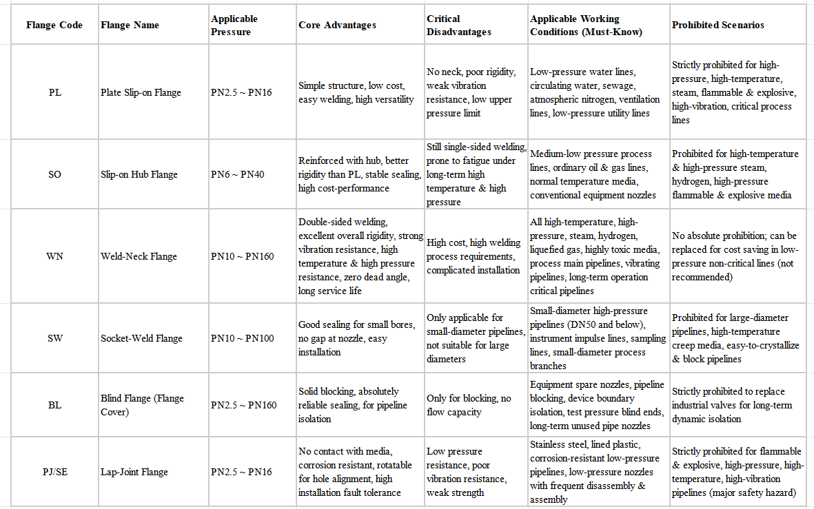
Six flange types cater to 99% of piping, equipment and valve connections within chemical plants: PL Slip‑on Flange, SO Slip‑on Hub Flange, WN Weld‑Neck Flange, SW Socket‑Weld Flange, BL Blind Flange and PJ/SE Lap‑Joint Flange.
They differ greatly in pressure resistance, applicable working conditions, suitable media as well as merits and drawbacks. The following table serves as the definitive reference for on‑site selection.
Flange Selection Rules:
1.PL (Plate Slip‑on Flange): Only for low‑pressure service‑water lines.
2.SO (Slip‑on Hub Flange): Applied for medium‑pressure regular process pipelines.
3.WN (Weld‑Neck Flange: Mandatory for high‑temperature, high‑pressure and hazardous‑media pipelines.
4.SW (Socket‑Weld Flange): Adopted for high‑pressure service with small‑bore size ≤ DN50.
5.Strict Prohibition: PL flange and PJ/SE lap‑joint flange shall never be used for pipelines containing flammable‑explosive media, hydrogen, liquefied‑hydrocarbon and steam.
Part 3: Five Types of Flange Sealing Faces Explained|90% Leaks Stem from Wrong Sealing‑Face Selection
No‑matter how premium the flange or well‑executed the welding is, wrong sealing‑face selection renders all your efforts futile.
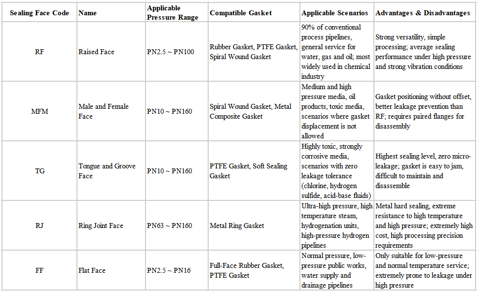
HG/T20592 specifies five mainstream sealing‑face types. Each matches designated pressure ratings, working media and gaskets and they must never be improperly combined.
Pitfall‑Avoidance Guidelines:
1. TG (Tongue‑Groove Face) is mandatory for toxic and highly‑toxic media to eliminate micro‑leakage completely.
2.RJ (Ring‑Joint Face) shall be adopted for ultra‑high‑pressure, high‑temperature steam and hydrogen‑service working conditions.
3.MFM (Male‑Female Face) is preferred for conventional medium‑and‑high‑pressure process pipelines.
4.RF (Raised Face) or FF (Flat Face) shall be uniformly applied for low‑pressure utility lines.
Part 4: PN (EU‑Standard) vs Class (US‑Standard): Do Not Mix‑Match Ratings
A common‑yet‑basic on‑site mistake is mismatching PN ratings (European standard) with GB standard and ASME Class (American standard).
Over 95 % of domestic chemical plants in China adopt the PN‑series per HG/T20592 (European‑standard system):
Low‑pressure: PN2.5, PN6, PN16
Medium‑pressure: PN25, PN40
High‑pressure: PN63, PN100, PN160
Imported equipment and foreign‑invested facilities usually follow ASME Class ratings. These two systems cannot be interchanged or assembled together. Their bolt‑hole spacing and sealing‑face dimensions differ completely, and forced assembly will definitely result in leakage.
Part 5: Non‑Negotiable Rules for Flange Selection (Severe Hidden Risks)
1. PL plate slip‑on flanges and lap‑joint flanges are strictly prohibited for pipelines carrying high‑temperature steam, hydrogen and liquefied hydrocarbons. Violations will be inspected by safety‑supervision authorities.
2.WN weld‑neck flanges must be installed at pump inlet and outlet with heavy vibration. Slip‑on‑type flanges will crack and leak under long‑term vibration.
3.RF raised‑face flanges shall not be used for toxic‑media pipelines. Gasket offset may easily cause leakage and poisoning accidents.
4.Non‑metallic full‑face gaskets are forbidden for high‑pressure service; spiral‑wound metal gaskets or metal ring gaskets are mandatory.
5.SW socket‑weld flanges are preferred for small‑bore instrument impulse lines to eliminate leakage points caused by threaded connections combined with low‑pressure flanges.
6.BL blind flanges shall be used for solid‑blocking of long‑term‑unused pipe nozzles and spare equipment nozzles. Isolation merely by valves is forbidden.
Part 5 : Team‑Summary
Although flanges seem to be the simplest piping components, they serve as the primary sealing line‑of‑defense for chemical‑process safety.
Persistent leakage and repeated maintenance‑rework for most facilities stem not from poor construction work, but from non‑standard design‑selection, mismatched sealing‑faces and inadequate pressure ratings.
Bear this core principle in mind: Do not over‑specify for low‑pressure service; never cut corners for high‑pressure conditions; make no compromises for hazardous media; and reinforce connections for vibration‑prone pipelines.